Instrumentation drawing piping diagrams diagram flow symbols control read interpret ids
Table of Contents
Table of Contents
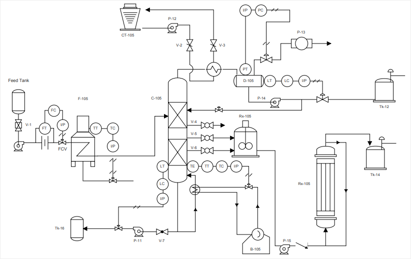
If you’re working in the engineering or construction industry, you’re likely familiar with Process and Instrumentation Diagrams (P&IDs). But, understanding how to draw a P&ID can be a different story. Whether you’re new to the industry or looking to improve your skills, this article will guide you through the process of creating a P&ID from scratch.
Creating a P&ID can be a daunting task, especially for those who are new to the industry. Understanding the symbols, terminology, and layout can feel overwhelming. But, fear not, with a bit of guidance and practice, you can become proficient in creating P&IDs.
The first step in drawing a P&ID is to understand the purpose of the diagram. Essentially, a P&ID is a detailed illustration of piping and instrumentation used in the process industry. It shows the piping, valves, pumps, instruments, and other equipment used in the process. The primary function of a P&ID is to provide a clear and comprehensive description of the process to be used in the construction, operation, and maintenance of the plant.
To create a P&ID, you need to have a thorough understanding of the process being used. Once you have this understanding, you can begin to layout the diagram. Start by sketching out the basics of the process, including the equipment and instrumentation required. From there, you can add in the necessary details, such as piping and valve connections.
My Experience with Drawing P&IDs
Before I became familiar with P&IDs, I found them to be intimidating and confusing. However, with time and training, I learned how to create accurate and comprehensive P&IDs. One thing that helped me was daily practice. The more P&IDs I created, the more I understood their purpose and the symbols used.
The Importance of Accurate P&IDs
Creating accurate P&IDs is crucial to the success of any project. A mistake in the design of the P&ID can result in costly errors during the construction or operation phase. It’s essential to have a thorough understanding of the process and equipment to ensure that the P&ID accurately reflects the system requirements.
Components of a P&ID
A P&ID typically includes the following components:
- Process equipment, such as tanks and reactors
- Pipes and valves
- Instrumentation, including sensors, transmitters, and controllers
- Safety features, such as pressure relief valves and emergency shutdown systems
Understanding P&ID Symbols
An essential aspect of understanding how to draw a P&ID is knowing the symbols used to represent different components. Each symbol represents a specific piece of equipment or process. A comprehensive list of P&ID symbols can be found online, and some software programs even come with built-in databases of symbols.
Creating a P&ID Step-By-Step
Now that you have a basic understanding of what goes into a P&ID and the importance of accuracy, let’s dive into the step-by-step process of creating one.
- Start with a sketch of the process and equipment layout
- Identify the equipment and instrumentation required
- Add in the necessary piping and valve connections
- Include safety features and emergency shutdown systems
- Double-check your work for accuracy
Question and Answer
Q: Can I create a P&ID without knowing the equipment and process?
A: No, it’s crucial to have a thorough understanding of the process and equipment involved to create an accurate P&ID.
Q: Can I use software to create a P&ID?
A: Yes, many software programs allow for the creation of P&IDs, and some even come with built-in databases of symbols.
Q: Why is accuracy important in creating a P&ID?
A: A mistake in the P&ID can result in costly errors during the construction or operation phase of the project.
Q: Can I learn how to create a P&ID on my own?
A: Yes, with proper research, practice, and training, you can become proficient in creating P&IDs.
Conclusion of How to Draw a P&ID
Understanding how to draw a P&ID is a crucial aspect of working in the engineering or construction industry. With practice and training, anyone can learn to create accurate and comprehensive P&IDs. Remember to have a thorough understanding of the process and equipment, and be diligent in double-checking your work for accuracy. By following these steps, you’ll be well on your way to creating professional-grade P&IDs.
Gallery
Learn How To Read P&ID Drawings - A Complete Guide

Photo Credit by: bing.com / read drawing piping instrumentation pid diagram drawings pefs guide learn rs
Piping And Instrumentation Documents - Instrumentation Tools | Piping

Photo Credit by: bing.com / piping instrumentation instrumentationtools logic
How To Read A P&ID Drawing Quickly And Easily | EdrawMax Online

Photo Credit by: bing.com /
P&id Diagram Basics

Photo Credit by: bing.com / diagrams
How To Read And Interpret Piping And Instrumentation Diagrams (P&ID

Photo Credit by: bing.com / instrumentation drawing piping diagrams diagram flow symbols control read interpret ids


